


aeration systems (page 2)
submerged mechanical aerators
The major difference between this type of appliance and surface aerators is that the former inject air direct into the core of the liquid mass.
They consist of:
- a motor:
- a rotating turbine or a pump;
- an air diffusion device.
Depending on the type of technology, self-suction aerators can be used; that is to say that they do not require a pressurised air input. Conversely, some designs will only work with an air input.
Their SAEs are variable. They improve with a pressurised air input.
Their advantages lie in they are simple to use and, above all, easy to maintain, when compared with a pump. Additionally, they are often easy to install.
Turbine or pump impellers must be designed so that they are not sensitive to blockage by various plastic material bodies or others particles that can be found in tanks and in certain cases for specific industrial effluent in order to withstand abrasion and/or corrosion.
Not sensitive to chemical products, these aerators are particularly well suited to industrial type water but can also be installed to advantage on urban wastewater applications.
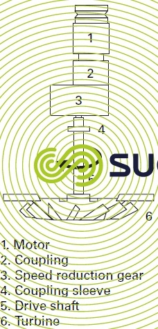
submerged turbine aerator
Turbines must be designed to operate in a two-phase mode (air + water) and must not be susceptible to fouling (this equipment, in particular, may be sensitive to fibers plant fibres).
Air is injected into the turbine which divides the air into bubbles before diffusing it. By propelling the water or air-water mixture at high speed, the turbine generates small to medium size bubbles.
Mixing is particularly efficient because the energy is generated very close to the tank floor (thus avoiding the formation of deposits); the air is then dissipated throughout the entire tank (good homogenisation). The submerged turbine aerator’s range of action exceeds 10 to 15 m for the larger models.
Efficiency depends heavily on tank geometry and on interaction between machines. In particular, proximity to a wall or to another appliance will considerably reduce oxygen transfer due to the high rising current that is created.
Submerged turbine aerators can be installed in depths of over 10 m. As their speed of rotation is low, this preserves the floc. The air flow can be regulated independently but, when a speed regulator is fitted to the turbine, this will ensure optimum efficiency under all operating conditions.
When their design allows, these units have the advantage of being able to operate in agitation mode only or in combined agitation/aeration mode. Consequently, the system is extremely flexible and adapts easily to treatment requirements.
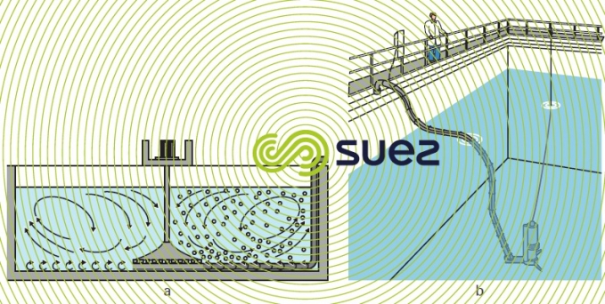

The emerged motor version is easy to maintain because no crane is required to lift the unit for routine tasks (figure 2.a). On the other hand, submerged motor installations are less expensive to install (figure 2.b).
These units have a very variable SAE depending on their design and utilization conditions such as their submersion depth: the turbine mechanical drive power does not vary much with submersion; the greater the submersion depth, the less the effect of this fluctuation on the SAE.
Furthermore, it has been seen that these technologies present good SAE when they operated in low volumes (high turbulence facilitates the good performance of these machines).
Under favourable conditions, the SAE levels can reach up to 2.2 kgO2 · kWh–1, for an SAE of 1.8 kgO2 · kWh–1. However, in unfavourable conditions the SAE observed may only be 1 kgO2 · kWh–1.
The following constitute the main advantages of the submerged turbine:
- good oxygen transfer efficiency if the facility's conditions are favourable;
- flexible aeration capability;
- ease of maintenance;
- not very sensitive to the composition of the effluent;
- SAE remains unchanged over time.
Some of these aerators can operate in self-suction down to submersion depths of approximately 4 metres and, accordingly, can operate without air blowers but at a lower SAE.
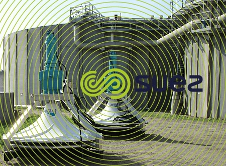
examples of submerged mechanical technology
system with hyperboloid turbines
These aeration turbines were developed and optimised for mixing only, initially in industrial water treatment plants. Then a version with an aeration function was developed using a torus pierced with holes through which compressed air is fed and with shearing vanes positioned under the turbine.
Indeed, the fact that they operate at low speeds (less than 60 rpm) makes them a very good solution to reduce the destruction of bacterial flocculent to a minimum.
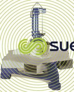
systems with rotors pierced with air distribution holes
The liquor below the machine is pumped by the rotor and the air bubbles are dispersed in the effluent around the holes in the rotor thereby enabling the air to be sheared. The aerated liquid is then ejected into the tank via channels in the stator located all around the machine. Low speed rotation ensures that the flocculent is kept in suspension and mixed.
These machines are generally robust and suited to both municipal and industrial environments and comply with syncopated aeration processes because they can work under continued or intermittent aeration. Via a semi-rigid tube, the machine is supplied with compressed air which passes through the distribution chamber in the stator and enters into the rotating rotor before being diffused into the tank.
Venturi effect aerator or hydro-ejector
Instead of being injected at the impeller, air is injected at a mixer, often through a Venturi in order to combine a high mixing speed with a suction effect. The mixture comprising water and fine or medium size bubbles is then expelled into the liquid mass through a nozzle (figure 3).
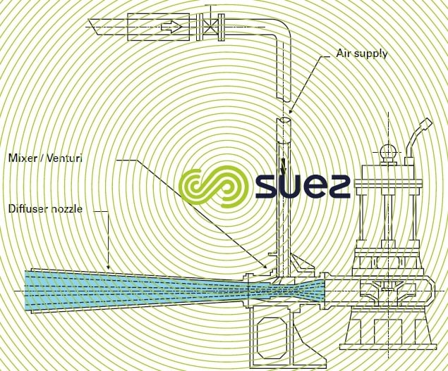
The pump can be submerged or emerged and can also supply one or more Venturi-nozzle pairs. The advantage of using several injectors is that mixing will be improved by reducing dead spots. In the auto-suction version SAE is around 1 kgO2 · kWh–1.
In the compressed air version, SAE varies from 1.2 to 1.7 kgO2 · kWh–1.SAE varies from 1.2 to 1.7 kgO2 · kWh–1. These aerators are often used in conjunction with a permanent pure O2 input or an O2 enriched air system in order to cope with seasonal pollution peaks. When pure oxygen is used, SAE can rise to 5 kgO2 · kWh–1.
surface aeration
the different appliances
Surface aerators can be divided into three groups.
The two most important of these are the slow speed aerators:
- the vertical axis versions that may or may not draw up water through a shaft and then spray it out sideways into the air;
- the horizontal axis versions (oxygenation roller or brush) that use the submerged section of their blades to sweep the water before spraying it out backwards.
The third group comprises high-speed, vertical axis aerators that are driven direct by a 750 or 1 500 rpm-1 electric motor without intermediate reduction gear. The mechanical unit is often supported by one or more floaters so that it merely rests on the water and is extremely mobile. This type of aerator has the advantage of being inexpensive but very energy-hungry (the specific O2 input rarely exceeds 1.2 kg · kWh–1 net) and has a low mixing capacity. It is better suited to lagooning applications than to activated sludge tanks where the formation of deposits needs to be avoided.
These units are produced for a 2 to 50 kW output range.
vertical axis and slow speed aerators or slow surface turbine
This type of appliance is as old as the activated sludge process.
These aerators have the following advantages:
- simple to install and operate;
- average energy efficiency;
- their mixing options (providing that very stringent installation conditions are met).
Slow surface turbines (figure 4) in general present the 4 kW to 125 kW range. Several thousands are currently in service. However, they are being used less and less because of their average AAE and of the nuisances they create (aerosol spray and noise). However, these nuisances can be limited by the judicious use of a covering over the stack together with soundproofing for the reduction gear unit.
the moving unit
The moving body d’une turbine de surface of a surface turbine (figure 5) can be:
- either an open impeller, eliminating any danger of fouling. It comprises an enclosed hollow hub to which are attached the thin, streamlined pumping blades and the stack’s dispersion blades.
- a rotor made from reinforced fibre glass and filled with expanded polyurethane foam with a contoured shape in order to accelerate fluids from its centre.
With a speed of rotation in the region of 100 rpm for the small units and 37 for the large versions (90 kW), peripheral velocity varies from 4 to 4.5 m · s–1. Restricted power operation is feasible using a two-speed motor or a speed regulator.
installation
The unit is often mounted on a fixed base, walkway or circular platform (photo 10) that can be girdled by a semi-rigid anti-spray and noise-proofing barrier.
Floating versions also exists, particularly suitable for cases where there is differential volume draw down in the equipped tank
energy efficiency – mixing utilisation conditions
SAE will vary from 1.6 to 1.8 kgO2 · kWh–1 for an AAE of 1.3 kgO2 · kWh–1. Anti-rotation baffles will be required to achieve optimum oxygen transfer efficiency.
In order to achieve effective mixing, water depth is restricted to 4.5 m.
horizontal axis and slow speed aerators aeration brush
These units are similar to vertical axis aerators in that an overhead spray is used for oxygenation simultaneously with mixing generated by the motion of the liquid. The brushes are designed for use in aeration tanks constructed in the form of moderately deep, oblong or annular ditches in which they create a circular horizontal flow.
moving unit
The brush moving unit (photo 11) consists of an 700 to 1 000 mm diameter brush that is between 1 and 9 m long, useful, bearing vanes mounted on rings so that they present an open profile in the direction of rotation.
The brush is held by two considerably over-sized end bearings each thoroughly sealed and protected from splashing by housings. Upstream and downstream hoods can be added to the installation and reduce the noise level and the formation of fine spray.
energy yield – conditions for mixing
Generally, tanks must have a minimum depth of 1.5m and a maximum depth of 3.5m (more is possible but special measures are required).
The minimum specific aeration efficiency ( SAE ) is 1.8 kg O2 · kWh–1. Oblong-shaped channels with solid straight lines give the best aeration performances ( SAE is higher than 2 kg O2 · kWh–1).
In UWW applications, this system has a specific output of approximately 35 W · m–3 used for oxygenation and mixing purposes.
air generation
Air generation constitutes an important aspect of pressurised air mechanisms and, sometimes, of submerged mechanical aerators. Submerged aerators and diffusers typically have submersion depths that range from 3 to 8 m, requiring the use of medium pressure range machines.
The type of machine recommended mainly depends on the size of the plant and on its air requirements as well as on the type of diffuser used.
Positive-displacement or centrifugal blowers are used. Both have very different operating ranges and principles.
volumetric machines
These machines have a virtually vertical pressure/output curve (figure 5). This means that their air pressure remains almost constant regardless of back-pressure. A fixed volume of air is compressed at each motor revolution. Capable of supplying the same amount of air under any circumstances, these machines are particularly appropriate for use with diffusers where head loss changes over time. On the other hand, output variation requires the option to modify the speed of rotation by installing a speed regulator.
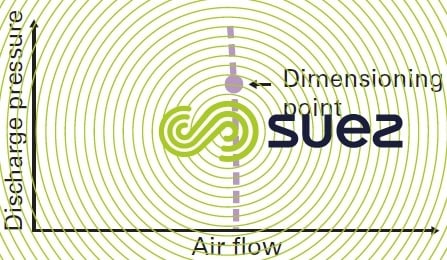
A very slight downward curve should be established (the less pressure there is, the higher the flow rate).
technologies
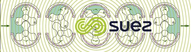
Three lobes rotary piston blowers (even two lobes, but these are almost never found), are positive displacement units. Figure 6 provides a schematic diagram of their operating principle.
With the larger units, output can reach 10 000 m3·h–1 for a maximum delivery pressure of approximately 950 mbar; consequently, they are appropriate for use in tanks having a 8 m (maximum) water depth. Their efficiency is in the region of 70 %.
One of the restrictions applicable to these blowers is the delivery air temperature. As a rule, this temperature, caused by gas compression, will be approximately 135°C. If this temperature is exceeded, the machine may rapidly be destroyed. That is why it is essential that diffuser head loss at the end of their service life be taken into consideration when these blowers are being sized.
We also need to note that a drop in the speed of rotation (using a speed regulator, for instance) will also tend to increase heating.
The screw compressor derived from a more high pressure technology (5 bar and above) can be used in tanks that are 8 m and more deep, especially today with the development of low pressure screws. Its sturdy construction and excellent efficiency (up to approximately 80%) make this an ideal machine for Flexazur fine bubbles diffuser operation and, in particular for programming and scheduling replacement over a number of years.
installation
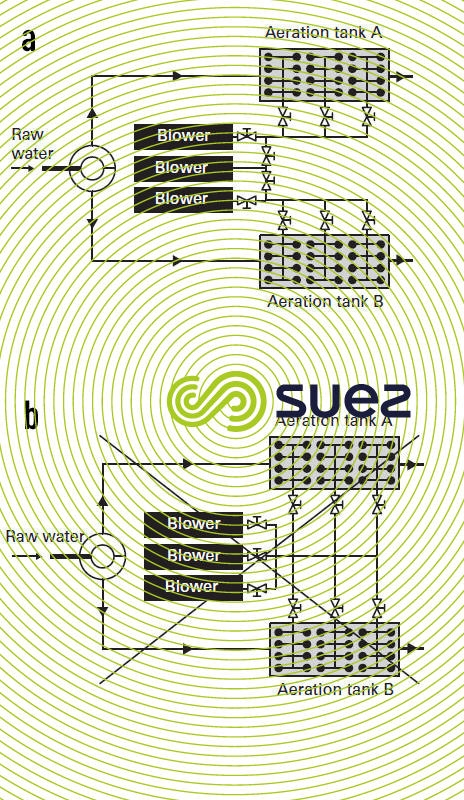
L’installation idéale consiste à dédier un ensemble de production d’air (une, deux ou trois machines) à un bassin uniquement.
L’installation figure 7.a est la seule recommandée.
En effet, le schéma de la figure 7.b aboutit inévitablement à un déséquilibre des débits et donc de la capacité de traitement. En premier lieu, parce qu’il est impossible d’installer les diffuseurs exactement à la même immersion dans deux bassins, les radiers et les niveaux de déversoir étant différents. Ensuite, parce que le tassement différentiel des ouvrages et l’évolution des pertes de charges n’étant pas identiques d’un bassin à l’autre, l’air ne peut pas être correctement distribué.
centrifugal machines
In this instance, the output delivered is highly dependent on the delivery pressure and has a flow rate/pressure curve as can be seen from figure 8.
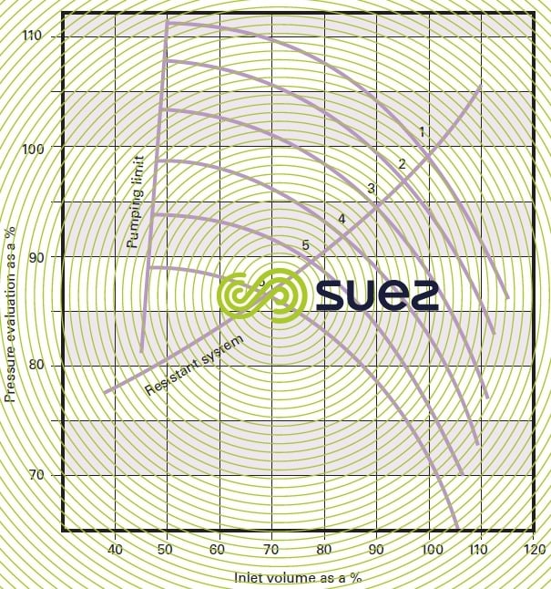
Consequently, this type of machine is ideal for use with diffusers whose head loss remains steady over time. A regulating valve can easily be installed to control flow rate during suction and even fluctuations in speed, etc... As shown in figure 8, the left hand side of the curve cannot apply. This zone, designated the pumping zone, is created because back pressure causes the air flow to reverse suddenly in the impellers. When operation borders on this zone, very strong vibrations occur, destroying the machine in a matter of minutes.
technologies
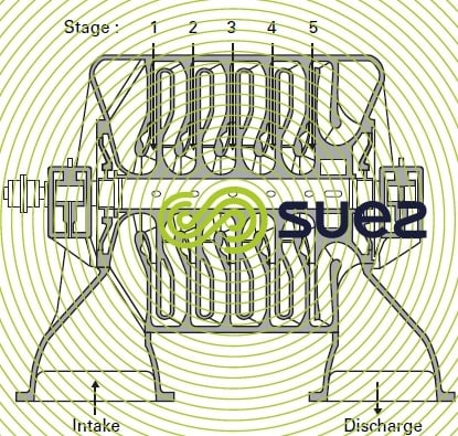
Multiple stage centrifugal blower: normal operating pressures require the use of several compression stages in series (figure 9). For speeds of rotation in the vicinity of 6,000 rpm and for a pressure reaching 1,000 mbar, output will usually vary between 1,000 and 30 000 m3 · h–1.
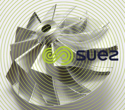
Turbocompressor (figure 10). This is a special type of centrifugal unit. Given its extremely high speed of rotation of 10,000 to 30,000 rpm, compression is achieved with one single stage. The output delivered by these units will range from 3,000 m3 · h–1 to more than 100 000 for a delivery pressure that can reach 1,200 mbar. Therefore, they are mainly used in plant greater than 200 000 p.e. Their excellent efficiency that can reach 85% significantly increases SAE. Additionally, some machines have an integrated, high performance output control system (in terms of energy) that provides excellent operational flexibility.
Within this category, two types of machines exist:
- Machines with set speeds which can achieve very high flow rates. They have a gear box allowing the operational speed to be achieved. Flow rate speeds can be set with two sets of vanes (optional) at the machine's entrance and at the impeller's outlet.
- Machines with speeds which can be varied may achieve flow rates of 14 000 Nm3·h–1
They are equipped with high frequency controlled permanent magnet motors and air or magnetic bearings in order to withstand the mechanical stress caused by high operating velocity.
installation
Due to its simplicity and reliability, figure 7.a. can be reproduced naturally. However, we can derive advantages from the major outputs and ease of flow rate control made possible by these machines. The type of installation illustrated in figure 7.b then becomes quite feasible and even recommended providing at least one flowmeter and one control valve is mounted on each tank’s main pipeline.
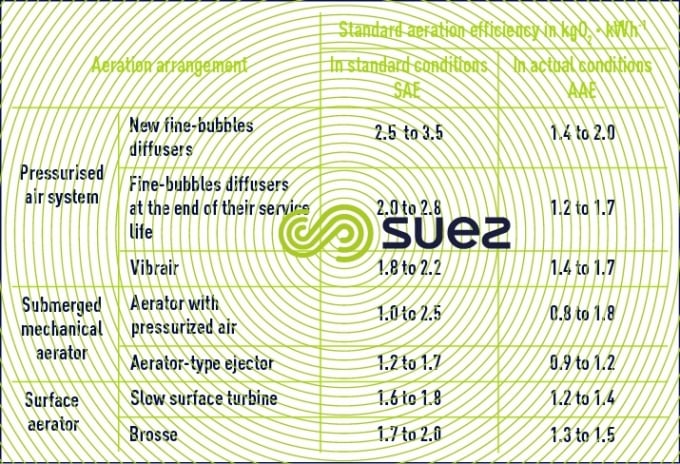
summary of aeration system performances
Bookmark tool
Click on the bookmark tool, highlight the last read paragraph to continue your reading later
